Sure you must have read all those glowing reports about this component, that cap blah blah blah. Ever wonder how true are those claims? Ever wonder whether it's really worth paying all the $$ for these "wonder" parts?
Have no fret! As DIY Paradise just completed a simple shootout between electrolytic capacitors. The target here is in the use in power supply decoupling. Test circuit as below. Pulse drives the base of the 2N3904 transistor and 2 points are monitored. The blue bubble labeled "scope green trace" and the red bubble labeled "scope yellow trace". If an ideal capacitor exists, then the capacitor under test will not show any ripple at all due to transistor switching on and off.
Credit for test circuit goes to YH and Thomas.
Test setup is a pain. At such high frequencies, even a few mm lead length will throw the whole thing off! I actually did this test twice. First time was done "on air", I just soldered the transistors to the caps. Results were very inconsistent, and not repeatable as well. Something must be wrong. Reason being the lead length of the caps were different and they were quite "far" from the transistor. How "far"? A few mm off! I revisited the setup. This time, using a breadboard. The caps and transistor were soldered on the board. I trimmed off the leads of the caps and pushed them down on the board, so that they sit snugly. I'm sure the lead lengths (and distance between cap to transistor) are equal this way. To change caps, I have to desolder them off. As you can see, it's really a pain going through all this.
And the results! If you are too lazy (or impatient) to look at these plots, go to summary page.
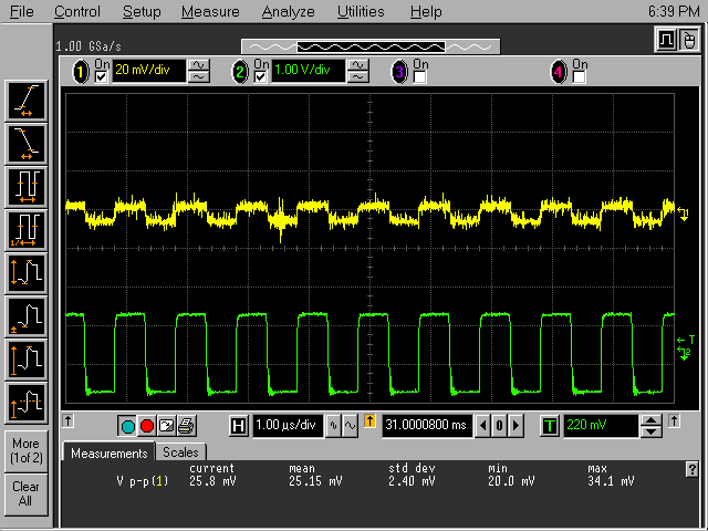
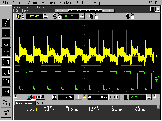
1MHz pulse
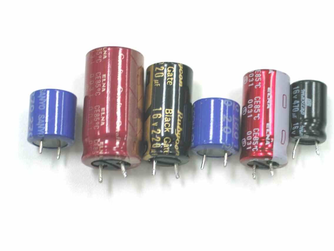
Generic "Max" electrolytic. 470uF 16V. Ripple of 81mV is measured.
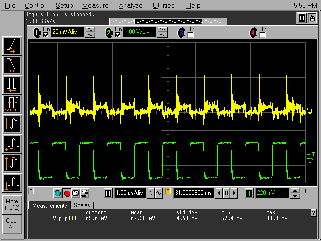
Elna Starget, 470uF 16V. Ripple 67mV.
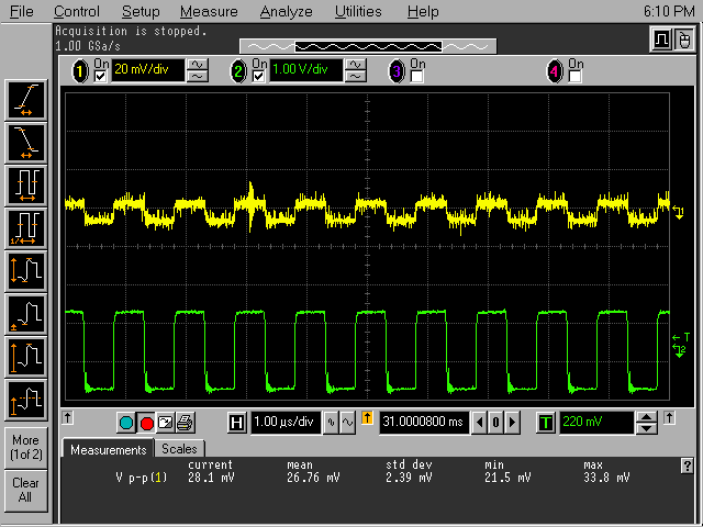
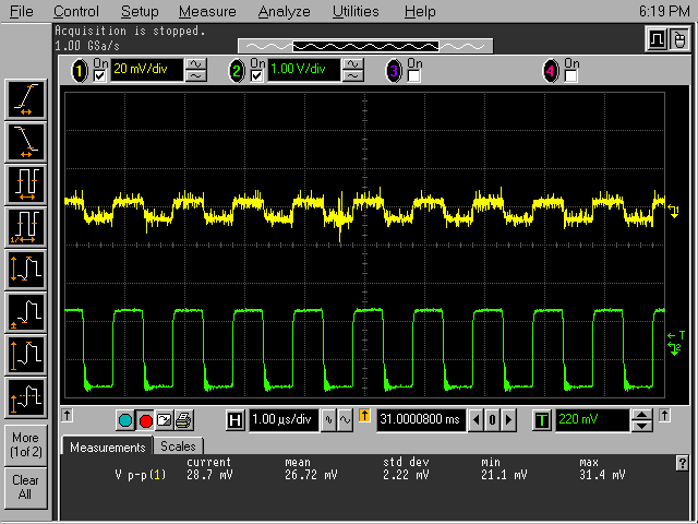
Elna Cerafine, 470uF 25V. 26mV.
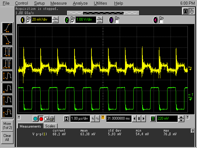
Black Gates, 220uF 16V. 63mV.
Sanyo Oscon. 180uF 20V. 25mV.
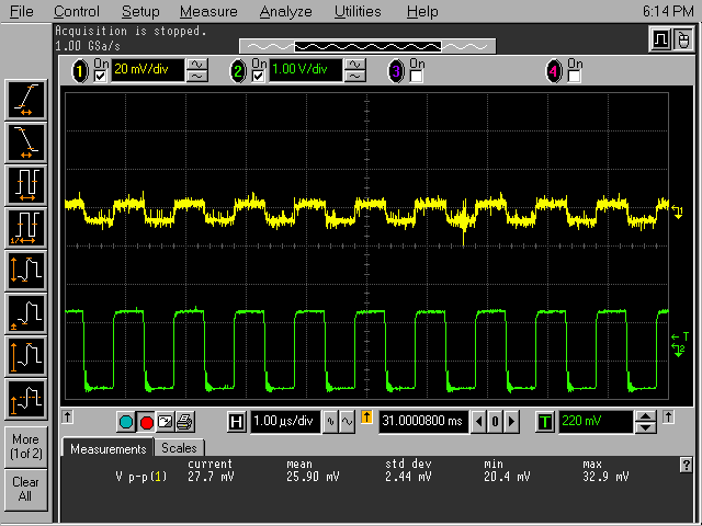
Sanyo Oscon. 270uF 16V. 27mV.
Sanyo Oscon. 470uF 10V. 26mV.