I have heard lots of good things about reclocking your CD player. Namely, taking out the clocking circuitry, powering it externally and feeding it back. But have been lazy to try it. The closest I did was the `clock hack', which is basically a re-arrangement of the clock circuitry. For a free tweak, this is really good!
But if you sit down and think about it (as though one can't think when standing up?), taking out the clock circuitry makes a lot of sense. In your CDP, the clock circuitry is most probably located very close to your DAC, sharing the same power supply. Now at frequencies >10MHz, the clock is going to pollute your power supply with its constant "on-off" switching. Don't think so? Look at this page. Look at what happens to your power supply as your clock switches. Your power supply is "singing in tune"! Terrible eh? So the very act of taking out the clock, powering it via a separate power supply is definitely going to improve things. Irrespective of whether you are using a better tolerance crystal. But then what remains is an issue of the clock power supply *doesn't*shouldn't* corrupt the power supply of the rest of your circuitry right? This is where the design of the power supply circuitry is critical. Sorry, ma friend. A simple 7805 definitely doesn't cut it here.
Anyway, among the many circuits out there, there is one raved by DIYers. And you can get the schematics by e-mailing the designer itself, Elso Kwak. A chemist by training, Elso has covered a lot of ground in this area. When I came to know about Elso's clock, it was version 2 then, and features only the driving circuitry. Later versions incorporate the power supply circuitry. But what's more amazing is that Elso is a very hands-on guy. He doesn't design by theory, but by ear. Yes, he listens. This is a very important fact as when designing, most techies would go for specs first, then sound. Not Elso though. Anyway, one day, I finally got serious and contacted Elso to build the latest version, which by now is Version 7. (now i'm finally "clocking" the clock)
OK. Parts wise, nothing is exotic here. You could get most of your parts from Farnell. Here are the order codes.
NPN transistor BC550C 316-3246
PNP transistor BC560 434-863
RF JFET J309 740-949
Comparator AD8561AN 314-5920
Shunt regulator TL431CLP 411-838
Other than the above, you need some inductors, ferrite beads (323-4885) and resistors. Of course, for power supply, I'm using my favourite "digital cap" - Sanyo Oscon.
All in all, I spent less than RM50 for all these parts.
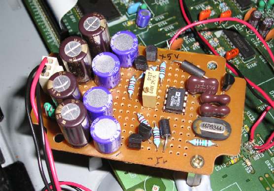
This being a truly DIY project, there's no PCB available. You could of course fabricate it yourself but if you are cheap and lazy (like me), try this. Get those small protoboards, preferably without traces. Layout components carefully, and use their leads as "wires". Paste some copper tape for better grounding. When you are done, try to cover the "unused" areas with copper tape. Oh yeah, ground it as well. Voila!
Anyway, I did all the above and implemented in my Marantz CD63. Other than Oscons, I used some Elna Silmic as well (which I ripped off my CD63 when `upgrading' it). OK, here's the lowdown.
Power
You need +/- 9-16V raw DC supply to begin with. I tapped off caps C805-806. From here, I get +12V, GND and -12V. Looking back, it might be better to tap off the digital supply - caps C813-814. Please be careful here. Confirm with DMM first before soldering in the wires. It's disastrous to wrongly wire +12/-12VDC. From the power supply, I have 3 wires which terminate into a 3-pin female connector. The male side sits on the clock PCB. This way, when debugging/modifying later, you don't have to desolder the power supply. Just yank it out!

Building is relatively straightforward. Be careful with cap orientation, especially the negative supply side. I began by first building the power supply. Be careful with orientation of all the transistors, regulator etc. After completing the power supply, hook it up to make sure all the voltages are ok. Mine had a problem on the -ve voltage side. Thankfully I didn't wire the comparator in yet. Phew!
NPN BC550C. Pinout is viewing with leads facing you.

PNP BC560.
RF JFET J309.

TL431.

AD8561.

Wiring it up
If you don't have your CDP service manual, Elso recommends soldering a 1kohm resistor to these 2 pads (left vacated by RD02) and test by trial-and-error. Pick the one that works, and remove the 1kohm resistor then.
It took me one whole day to wire this up. That's because the board I'm using is way too small. 6cm x 4cm. And I'm using 8 electrolytics for the power supply. Stupid is as stupid does. Finished wiring, hooked it up but... the CD player can't even read the CD. Big trouble. As it was already late, I decided to call it a day, but what a rough night it was! I was troubled by this guy. In all my DIY adventures, my experience with building amps have always been "first time and it works" but not with digital circuits. Hmm. I think I have "analog fingers".
OK. Check it out next morning. Damn! Missed one resistor. Fix this and... voila! It works! Okay, the sound? Cleaned up the highs a lot. There's more prescence on the highs now. I used to think that my system's highs is already very clean, but the Kwak Clock cleaned it up even further. And I could hear more detail than before! Must be the effect of cleaning up the highs. Resolution is better! Soundstage appears to be wider but I'm not sure.
Hey! For parts cost of less than RM50, this is a good project!
Once you are done, you'll have one wire as output. See the CD63 decoder/DAC here? You need to remove the clock components, namely, CD02, CD03, RD02 and of course, XD01. After removing RD02, wire the clock output to the PCB hole left by it, the one connected to pin 28 (XT1). This is the clock input of this DAC chip.
